HS Code: 85
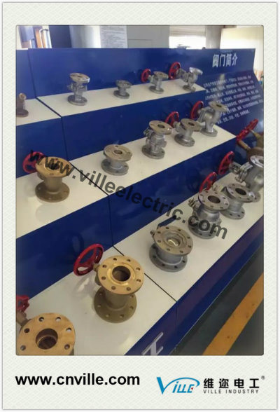
**Application**
This pressure relief valve is designed to work with electrical alarm signals for remote control. It is suitable for use in various electrical equipment such as gas or liquid-insulated transformers, instrument transformers, on-load tap changers, and high-voltage switches. In case of malfunction, the valve opens to relieve pressure, preventing damage to the oil tank and avoiding deformation or explosion. Once the pressure is reduced, the valve automatically closes to prevent water and impurities from entering.
**Working Conditions and Installation Mode**
- **Environment Temperature:** -30°C to 40°C
- **Installation Options:**
A) Installed on top of the oil tank
B) Installed on the side of the oil tank
C) Installed on a lifting pedestal
**Installation, Use, and Debugging**
- Connect the pressure relief valve to the tank using stud bolts.
- Ensure the bottom of the valve is well-sealed.
- When connecting the valve to the tank, tighten the bolts evenly to avoid damaging the valve base.
**Usage Notes**
- Remove the latch before the equipment starts operating.
- Ensure the pressure relief valve is functioning properly.
**Debugging Instructions**
- Manually check the switch signal for accuracy and sensitivity before commissioning.
- **Method:**
1. Measure the output signal of the switch when the pressure relief valve activates using a multimeter to verify it matches the switch’s marking.
- Example: "Common" to "Normally Open" should show an open state.
- "Common" to "Normally Closed" should show a closed state.
2. Simulate the valve's action by lifting the small red cap and check if the switch changes its signal accordingly.
- For a "Normally Open" switch, it should close.
- For a "Normally Closed" switch, it should open.
3. Check the connection between the signal switch and the control circuit.
- After testing, replace the small red cap to ensure the valve functions correctly and provides warning signals.
**Dimensions Table**
| Caliber of Oil-Gushing | D1 | D2 | D3 | D4 | H1 | H | Valve Pedestal Install Bolt Diameter × Quantity |
|------------------------|----|----|----|----|----|---|-----------------------------------------------|
| φ25 | φ46 | φ54 | φ90 | φ120 | 50 | 114 | M10×3 |
| φ50 | φ74 | φ83.5 | φ130 | 125×125 | 50 | 114 | M12×4 |
| φ80 | φ122 | φ133 | φ170 | φ200 | 50 | 128 | M12×6 |
| φ130 | φ172 | φ181 | φ235 | φ260 | 50 | 128 | M16×6 |
**Images**

**Our Best Service For You**
| 1. |
Pre-sale Service |
| a. |
Develop technical solutions |
| b. |
Send quotation, technical data sheet, and drawings |
| c. |
Prepare power transmission, testing, and shipping plans |
| 2. |
In-sale Service |
| a. |
Supervise manufacturing according to the plan |
| b. |
Send photos at each production stage (hold points) |
| c. |
Inform customer one week before testing |
| 3. |
After-sale Service |
| a. |
Installation, commissioning, and staff training |
| b. |
Quick response within 12 hours |
| c. |
Provide a 12-month warranty period |
**Welcome to Contact Us**

Concrete Mixer
concrete mixer
Mobile Portable Cement Concrete Mixer can turn over 360 degree at both sides when it works. The drum revolves for mixing and reverses for discharging.
Features:
1. Mobile Portable Cement Concrete Mixer adds a water pump for water circulation between water tank of the engine and the radiator, which keeps the engine water temperature to be stable.
2. To remove the air sucking point from the back to the front is able to avoid sucking the dust. It will be good to prolong the service life of the engine.
3. It has the advantages of compact structure, higher reliability, mixing evenly, big capacity, easy operation, easily movable between sites, etc. The reverse drum concrete mixing machine is widely used in building site, road and bridge project, and many other construction sites
Concrete mixers,Concrete Mixing Machine,Portable Concrete Mixer,Self Loading Concrete Mixer Truck
Shandong Nuoman Engineering Machinery Co., Ltd , https://www.chinanuoman.com