Control Basics: The Difference Between Sink and Source Logic
Wiring I/O for motion control can be intimidating, especially for someone who's new to the process. It's easy to feel nervous when you're dealing with electrical components that can cause serious damage if not connected properly. Even experienced engineers might get a little anxious before pressing the START button on a demo system—after all, Murphy’s Law is always in play.
The confusion often comes from different wiring terminology used by engineers and manufacturers. How do you know if you're comparing apples to apples? For example, is sourcing logic the same as PNP logic? Are we sinking or taking a sinked source? In our experience supporting motion control applications, we've heard it all. Most of the time, tech support engineers will direct you to a wiring diagram and advise you to follow it. But what do "sink logic" and "source logic" really mean? Let's break down the basics.| Terminology |
Electronic Circuit (Digital)
An electronic circuit consists of components like resistors, transistors, capacitors, inductors, and diodes, connected via conductive wires or traces on a PCB. It requires a voltage supply and ground, where ground acts as a reference point for measuring potential. A digital circuit uses DC voltage and operates with discrete on/off states. A DC power source flows from positive to negative.
I/O
I/O stands for Input/Output. In simple terms, it refers to any device that executes an output based on an input. For instance, a keyboard (input) and monitor (output) are examples of I/O. In motion control, I/O describes signal communication between devices using binary logic, such as between a PLC and a stepper driver.
Electrical Load
An electrical load is a component or part of a circuit that consumes electric power. This is the opposite of a power source, like a battery or generator. Examples include light bulbs and motors. Here, we're focusing on input circuits.
Logic Circuit
A logic circuit is an electric circuit whose output depends on its input. It may have one or more binary inputs (on/off) and a single binary output. It can consist of switches, relays, solid-state diodes, and transistors.
| Sink Logic vs Source Logic |
Sink and source logic circuits are commonly associated with PLC I/O signals and apply only to DC circuits. They differ in the type of components used and how current flows through the circuit.
- Logic is defined by the type of components in the circuit.
- Logic defines current flow in the circuit.
- Whatever logic you use for the output, the opposite is required for the input.
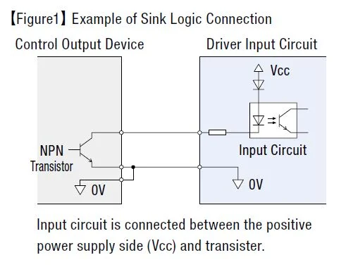
Sink Logic
In a sink logic circuit, an NPN transistor provides a path to ground for the electrical load. An NPN transistor needs to be connected to a PNP transistor to function correctly. So, a sink logic circuit must be paired with a source logic circuit.
Figure 1 shows a sinking digital output connected to a sourcing digital input. The input circuit is connected between the positive power supply (Vcc) and the NPN transistor.
Source Logic
A source logic circuit uses a PNP transistor to provide a path to voltage for the electrical load. A PNP transistor must be connected to an NPN transistor to work. Therefore, a source logic circuit must be paired with a sink logic circuit.
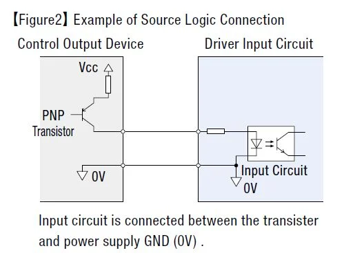
A useful mnemonic is to think of a source logic circuit as providing a path to the voltage source, while a sink logic circuit provides a path to ground.
| TIP : Compare wiring diagrams side by side |
|
When working with wiring I/O between a PLC and a servo or stepper driver, a helpful tip is to print out the wiring diagrams from both the PLC and the driver and place them side by side. This helps visualize the current flow from the voltage source to the load and back to ground. |
| Trace the Current Flow |
Many of my support calls were done remotely, which made wiring issues challenging. To avoid damaging customers' PLCs, I used to print out the wiring diagrams and trace the current flow from the voltage source, through the load, and back to ground. Supporting remotely also taught me the importance of knowing exactly which side of the I/O the customer was referring to.
To ensure a PLC sourcing output triggers a sinking input on the driver, everything must have the necessary power. Sufficient voltage and current should enter the positive terminal from the PLC side, pass through the output circuit, into the input circuit (the load), and then return to the ground of the power supply to complete the circuit. Each individual I/O signal on a PLC usually has two terminals: one for current going in and one for current going out. Sometimes, these terminals are grouped together and referred to as "common," which could either be the voltage source or ground.
| TIP: Don't forget power requirements for I/O |
| It's also important to pay attention to voltage and current requirements for both inputs and outputs. If the output calls for current-limiting resistors, use Ohm's Law to calculate your external resistance, but don't forget about the internal resistance. Remember that you have to meet both the voltage and current requirement of the input. |
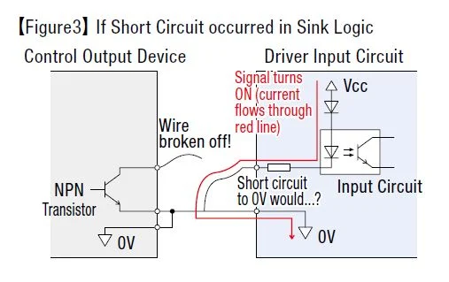
| Which is Safer? |
It's important to understand the type of logic or transistor being used to determine the correct wiring method. Additionally, there are safety considerations. If something goes wrong with the customer's device, causing an I/O signal line to earth leak or short-circuit the ground (0v) line, it could be dangerous.
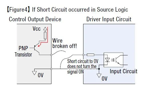
If source logic is used instead, the input circuit isn’t directly connected to the positive power side (Vcc). Therefore, an earth leakage or short circuit of a signal line won’t turn the input on. That’s why source logic is considered a safer option.
| Summary |
|
Sink and source are terms used to define the flow of direct current in an electric circuit.
Logic is defined by the type of components in the circuit.
A simple electronic circuit consists of one digital input connected to a digital output. To power the circuit, a voltage source, a ground, and a load are necessary.
|
| For Flexibility, Use Products That Offer Both Sink and Source Logic |
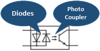
Certain products in the market offer both sink and source logic for flexibility in connections. This is possible due to bidirectional diodes wired in parallel. Photo couplers also help minimize wiring damage. These products are ideal if you need flexibility or plan to repurpose them later.
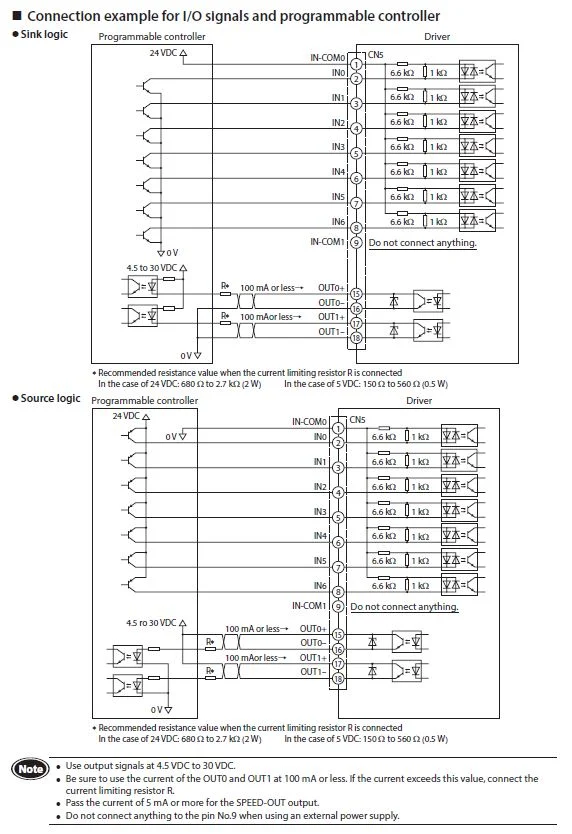
Here's what the actual wiring diagrams look like for the BLE2 Series brushless motor drivers. There is one diagram for connecting sink logic outputs and another for source logic outputs. The PLC is on the left, and the motor driver is on the right. The INx designations are inputs, and the OUTx designations are outputs.
Take a look at the first input "IN-COM0" (Inputs Common). On the top wiring diagram, it's connected to 24 VDC, and the input has a path to ground. On the bottom diagram, the "IN-COM0" is connected to 0v, and the input has a path to the voltage source. The bidirectional diodes in the input circuits allow this.
Most of our newer drivers offer both sink and source logic. If you need help locating them, please ask our helpful tech support engineers.
 hbspt.cta._relativeUrls=true;hbspt.cta.load(2284573, 'e64b3511-e058-4331-988a-7b02387c7450', {"useNewLoader":"true","region":"na1"});
Thanks for reading! Please subscribe for more updates.
Many Colors Pvc Yoga Mat,Pvc Yoga Mats,Yoga Mat,Customized Yoga Mat
Anyang Qunxiu Plastics co.,ltd , https://www.qunxu.com