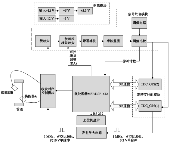
0 Preface In recent years, ultrasonic flowmeters have been widely used due to their non-contact type and fluctuating characteristics of fluids. For the time-difference type ultrasonic flowmeter, accurate measurement of the ultrasonic propagation time is the key to improving the measurement accuracy. On the basis of the current measurement chip precision has reached the ps level, the key to improving the precision of the time measurement is to accurately determine the ultrasonic wave. Shaped arrival time. The waveform of the ultrasonic signal is particularly critical for accurately determining the time at which the ultrasonic wave arrives. Under this premise, this paper designs a time-difference ultrasonic flowmeter and introduces the design ideas of its hardware implementation circuit. 1 Measurement principle The time difference method is a method for finding the flow rate based on the relationship between the propagation time difference of the ultrasonic wave in the fluid, and the flow velocity of the fluid to be measured. The essence is that the propagation speed of ultrasonic waves in the fluid is affected by the fluid flow, and the time measured in the forward flow and the reverse flow will be different. Therefore, according to the difference of the measured time, the flow velocity of the fluid can be calculated and calculated. Fluid flow. The schematic diagram is shown in Fig. 1. The installation angle of the countercurrent transducer and the forward flow transducer with respect to the axis of the pipeline is θ, the diameter of the pipeline is D, the linear distance of the two transducers is L, and the fluid velocity is v. Fig.1 Time Difference Method of Ultrasonic Flowmeter In the measurement, the countercurrent transducer and the downstream transducer alternately receive and transmit the ultrasonic wave. The actual propagation velocity c0 of the ultrasonic wave is the sum of the velocity of sound c and the velocity component vcosθ of the fluid in the vocal tract direction: C0=c±vcosθ (1) At this time, the forward current propagation time is: From the above equation, the time difference between forward and backward flows can be obtained as: Because the maximum measurable flow velocity of the general ultrasonic flowmeter is about 10m/s, and the propagation speed of the sound in the fluid is about 1500m/s, which is far greater than the fluid flow velocity, the time difference between the forward and backward flows can be approximated as: Correspondingly, the fluid flow rate formula can be expressed as follows: From formula (5), it can be seen that the measurement accuracy of the ultrasonic wave propagation time along the countercurrent directly affects the measurement accuracy and the measurement range of the flow velocity. 2 system hardware design System hardware structure shown in Figure 2. Figure 2 System hardware structure The system hardware mainly includes power module, signal transceiver module, signal processing module, timing chip measurement module, MSP430F1612 microprocessor module and system data acquisition module. The circuit design of several important modules is briefly described below. 2.1 signal processing module circuit design As shown in the hardware structure diagram of the system in Figure 2, the signal processing module includes five links: one-stage amplification, two-stage controllable gain amplification, band-pass filtering, half-wave rectification, and threshold comparison. One of the first-stage amplification and band-pass filtering are built using an OPA2725 op amp. The half-wave rectification circuit consists of a diode and a resistor. The second-controllable gain amplifier is implemented by a voltage-controlled gain amplifier VCA822. The four links are compared. Simple, so the following describes the specific structure of the threshold comparison circuit. The threshold comparison circuit is shown in Figure 3. The comparator uses the AD8611 from Ana-logDevices. The propagation delay is 4ns. When the input signal amplitude is higher than the reference level, the output QA outputs a high level. When the input signal amplitude is lower than the reference level, the output QA outputs a low level. Therefore, by connecting the ultrasonic signal to be processed to the signal input port and adding a reference level, a series of compared square wave signals can be output. The rising and falling edges of the square wave signal are the arrival times of the ultrasonic signals. The reference level required by the comparator is provided by the threshold circuit. The threshold circuit is formed by a combination of an instrumentation amplifier and an op amp. The instrumentation amplifier is a high precision instrumentation amplifier, IN114, with a gain of Figure 3 Threshold comparison circuit 2.2 Timing chip measurement module circuit design The square wave signal obtained through the signal processing module contains the time signal that the system needs to record. Accurately recording these time points for the microprocessor to do further analysis, judgment and calculation is a key part of the system flow measurement. Therefore, a timing chip with high measurement accuracy and fast response speed must be selected. This article selected a high-precision time measurement chip TDC-GP2 to achieve timing, TDC-GP2 has a high-speed pulse generator, stop signal enable and clock control functions, these function modules make it able to meet the various requirements of ultrasonic flowmeter measurement. Because here needs TDC-GP2 to measure the edge moment of square wave signal, including rising edge and falling edge, so need two pieces of time chip TDC-GP2 to realize the measurement of time, a piece of TDC-GP2 is set up as the rising edge is triggered, another piece is set up For the falling edge trigger, measure the first three rising edge moments and the first three falling edge moments of the square wave signal. Its application circuit design is shown as in Fig. 4. Figure 4 timing chip measurement circuit
Applications
Features
Technical Specifications
of Belt Dryer for Dehydration Vegetable
Vegetable And Fruit Belt Dryer Vegetable Belt Dryer,Apple Drying Machine,Fruit Drying Machine,Fruit Belt Dryer Jiangsu Yutong Drying Engineering Co.,Ltd , http://www.ytdryer.com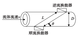
 (2)
(2)  (3)
(3)  (4)
(4)  (5)
(5)  (6)
(6) 
 The op amp is a high-speed op amp OPA2604. The op amp returns the output voltage of the IN114 to the reference voltage of the IN114 in a following manner.
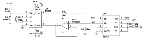

Our belt dryer is widely used for dehydration, drying of all kinds of seasonal
vegetables and fruits, such as garlic, pumpkin, carrot, konjac, yam, bamboo
shoot, horseradish, onion, apple, and so on.
This type of belt drying equipment offers high efficiency and low energy
consumption.
The drying area, drying temperature, air pressure, and belt speed etc. can be
adjusted so as to better suit vegetable quality requirements.
According to different characteristics of the vegetables, Auxiliary Equipment
is also available.